Using CODED FLOWS
Building Base Flows
A Base Flow in CODED FLOWS represents a processing pipeline built entirely using the visual flow graph editor. Unlike UI Flows (which we'll cover later), Base Flows do not launch a separate web user interface like Streamlit.They are ideal for prototyping scripts, defining core data processing logic, automating tasks, or managing backend processes that operate without direct user interaction after initiation.
In this guide, we'll walk through creating a simple Base Flow example: extracting the Red, Green, and Blue (RGB) color channels from an image and displaying each channel in separate "Image" bricks within the CODED FLOWS environment.
Creating Your First Base Flow Project
To start, you need to create a new project configured for Base Flows:
Open CODED FLOWS: Launch the application.
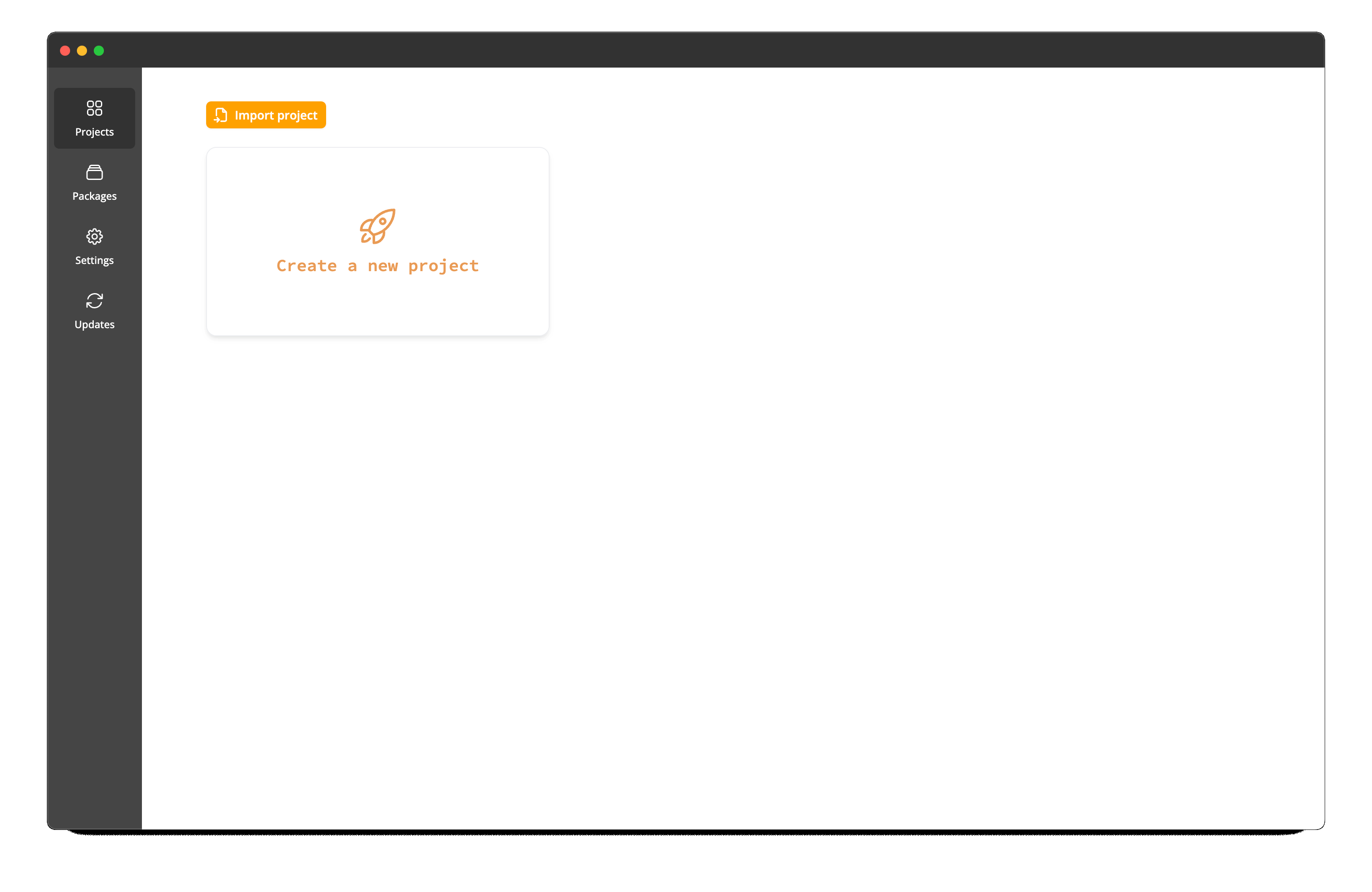
Create New Project: Click the "Create a new project" button to initiate the creation of a new project.
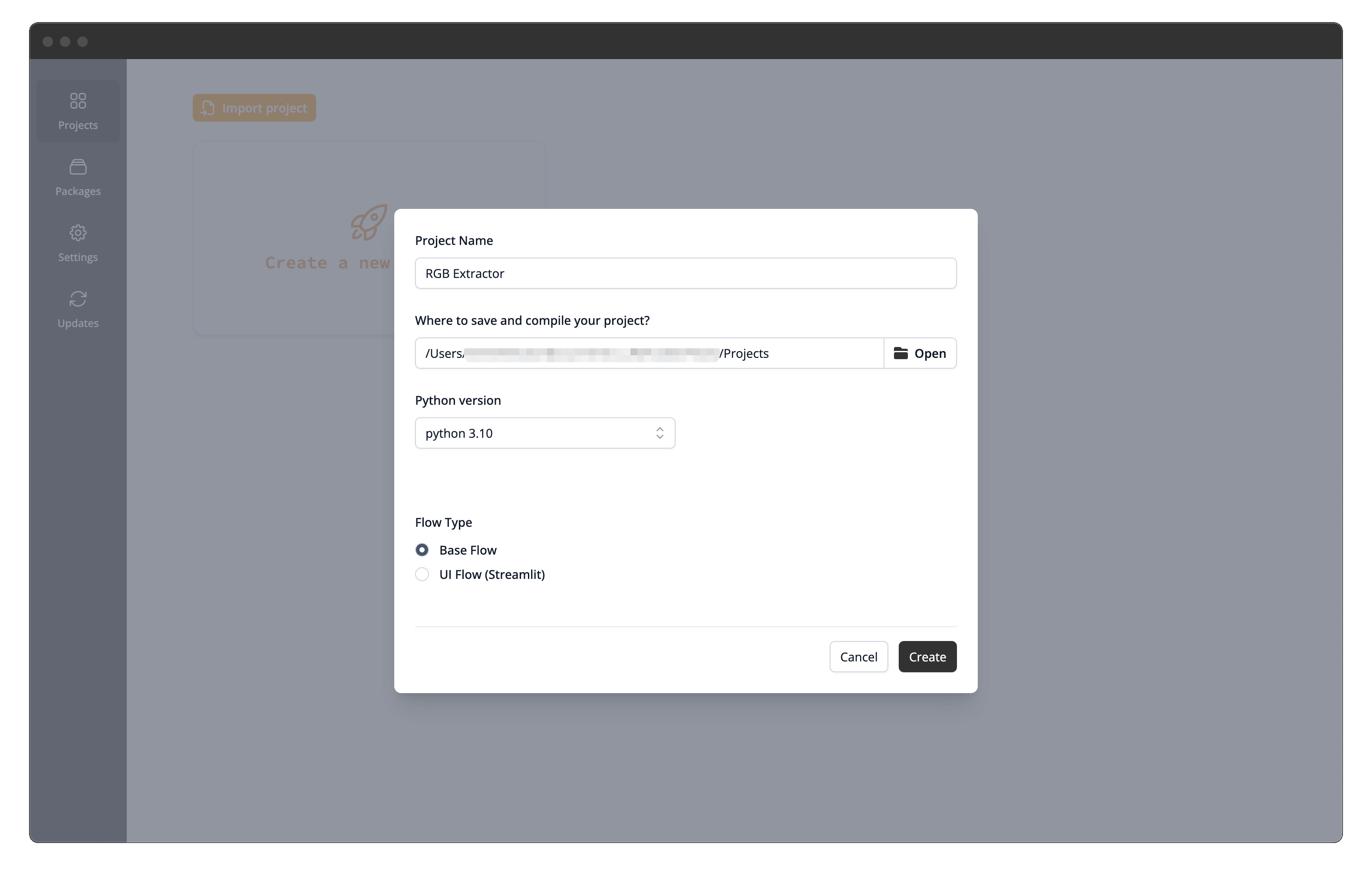
Configure Project Settings: A dialog will appear asking for the following details:
- Project Folder: Browse and select the directory where your project files will be stored.
- Project Name: Enter a descriptive name for your project (e.g., "RGB Extractor").
- Python Version: Choose the desired Python version for the project's environment from the dropdown list.
- Flow Type: Select 'Base Flow'.
Python Version Management
If the Python version you select isn't already available, CODED FLOWS will automatically download and set up a standalone version specifically for this project. This ensures your project runs in a consistent and isolated environment.
Create and Open: Click the "Create" button. CODED FLOWS will set up the project structure and open the flow graph interface for your new Base Flow.
Understanding the Flow Graph Interface
Before building the flow, let's get familiar with the main components of the editor:
Top Action Bar
Located at the top of the window, this bar contains essential controls:
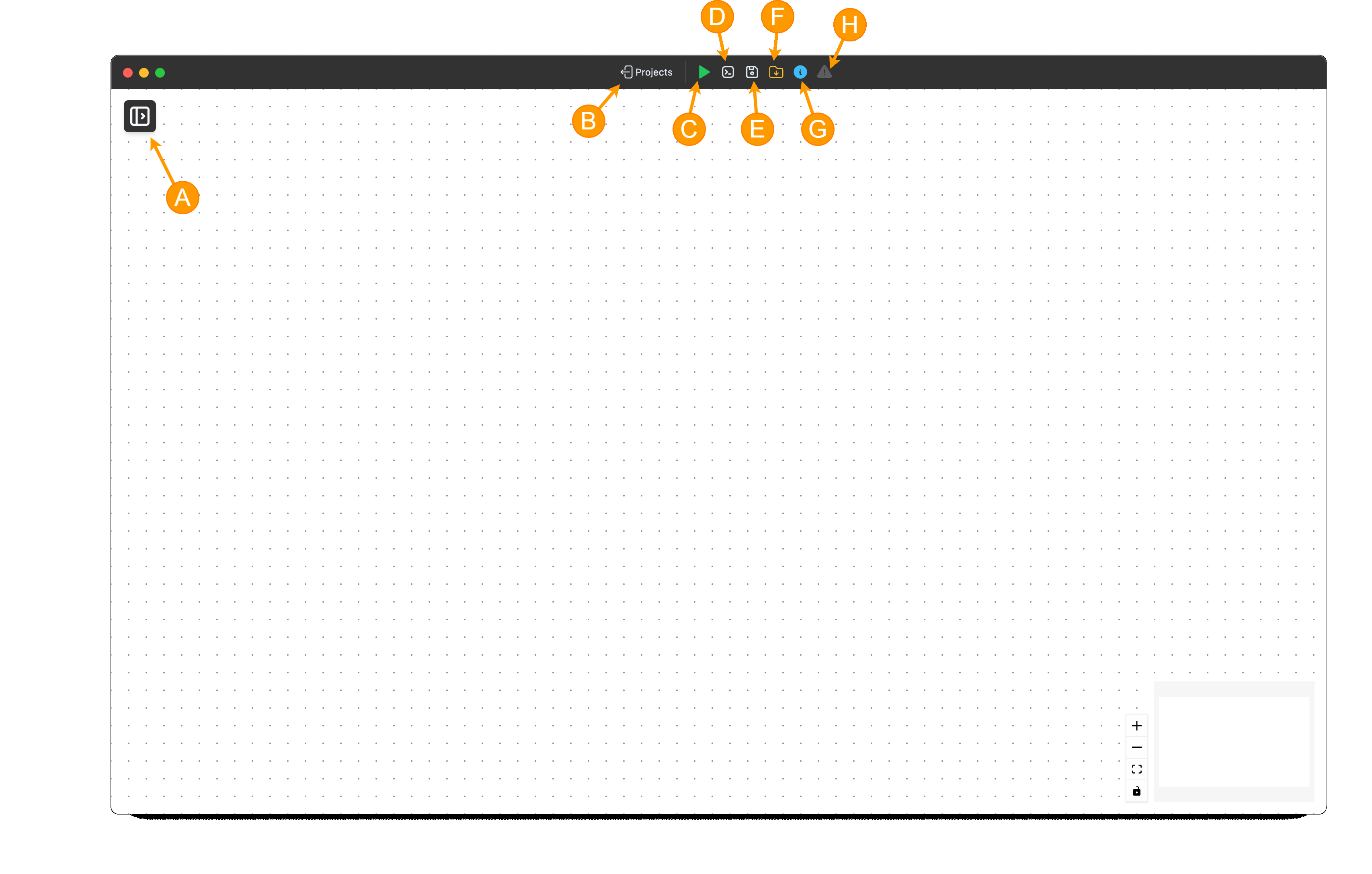
- (A) Toggle Sidebar: Click the Sidebar button to show or hide the sidebar.
- (B) Return to Projects: A button to go back to the list of your projects.
- (C) Execute / Stop: Buttons to start (run) the flow execution or forcefully stop it if it’s already running.
- (D) Logs: Opens a dedicated window or panel to display real-time execution logs for your flow.
- (E) Save: Saves the current state of your visual flow graph.
- (F) Open Project Folder: Opens the underlying project directory on your filesystem.
- (G) Save Script: Generates a standalone Python script equivalent of your visual flow.
- (H) Brick Info: Displays or hides a quadrant where information about a Brick is shown.
- (I) Error Indicator: An icon that signals if there are errors. Clicking it usually reveals the error messages.
- (J) Flow Status Indicator: A visual status box providing real-time feedback on the flow state.
Displaying Brick Information
To display information about a Brick, simply double-click its node or the Brick element in the sidebar.
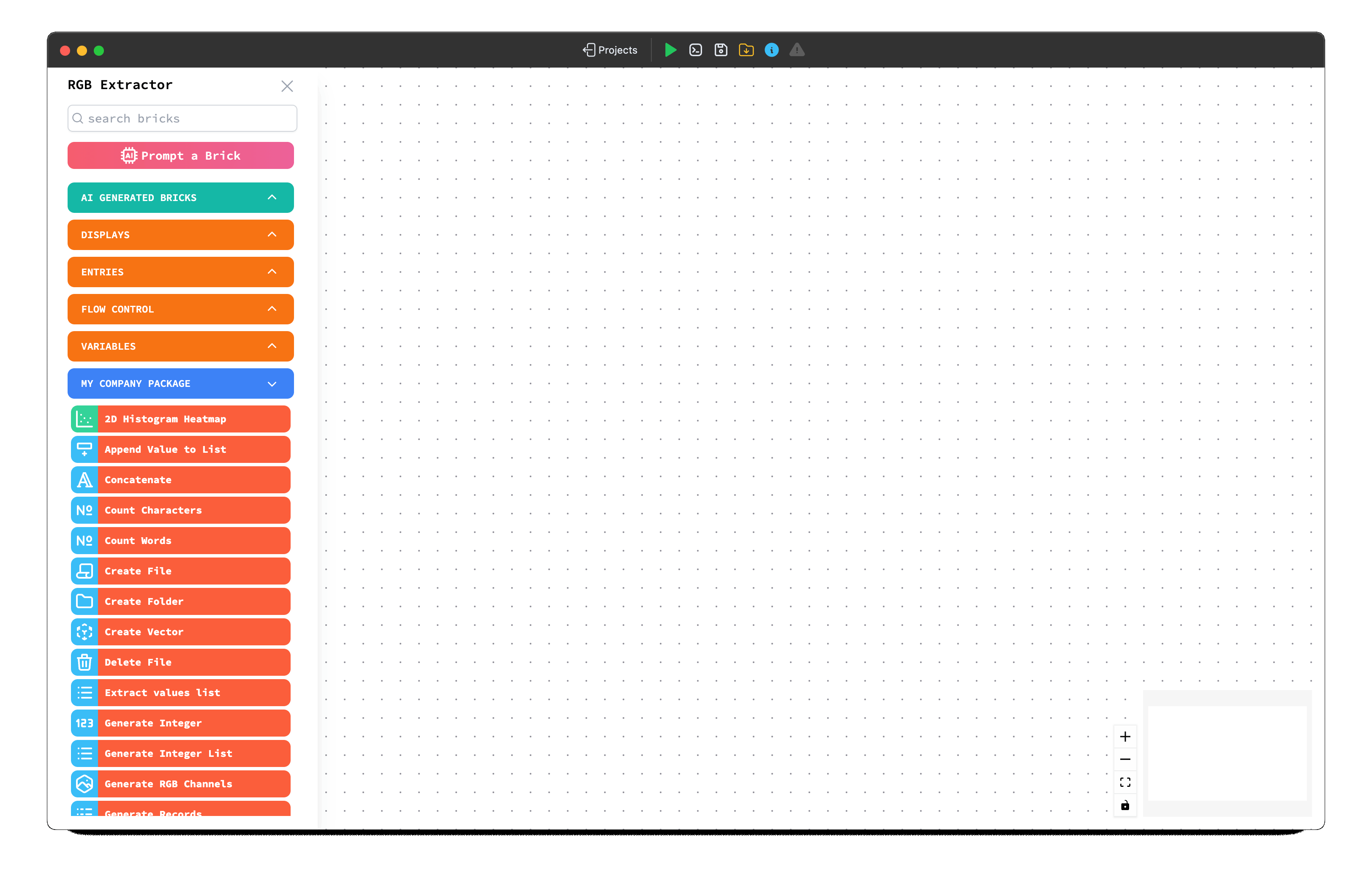
Sidebar
The Sidebar provides access to all the building blocks (Bricks) for your flows:
- Packages & Bricks: The sidebar lists available Packages (collections of related bricks). Click a package name to expand it and see the Bricks it contains.
- Search: Use the search field at the top of the sidebar to quickly find specific bricks by name.
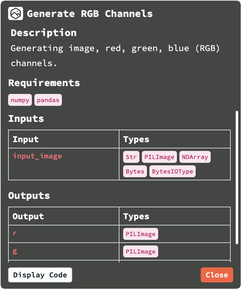
Brick Details
Double-click on a brick in the list. A Details Panel will appear (often docked in the top-left area). This panel shows:
- The brick's Description and its Pyhton requirements.
- Its Inputs and Outputs, along with their expected data types.
- A button to view the brick's detailed Documentation.
- A button to view the underlying Python Source Code of the brick's function.
Building the Example Flow
Now, let's construct the flow to extract RGB channels:
- Find Bricks: Use the sidebar's search or browse the packages to find the bricks needed for this task. You'll likely need:
- A file entry brick to select the image.
- A brick to load or specify an input image (
Read Image). - A brick to split the image into its color channels (e.g.,
Generate RGB Channels). - Four instances of a brick capable of displaying an image (
Image Display).
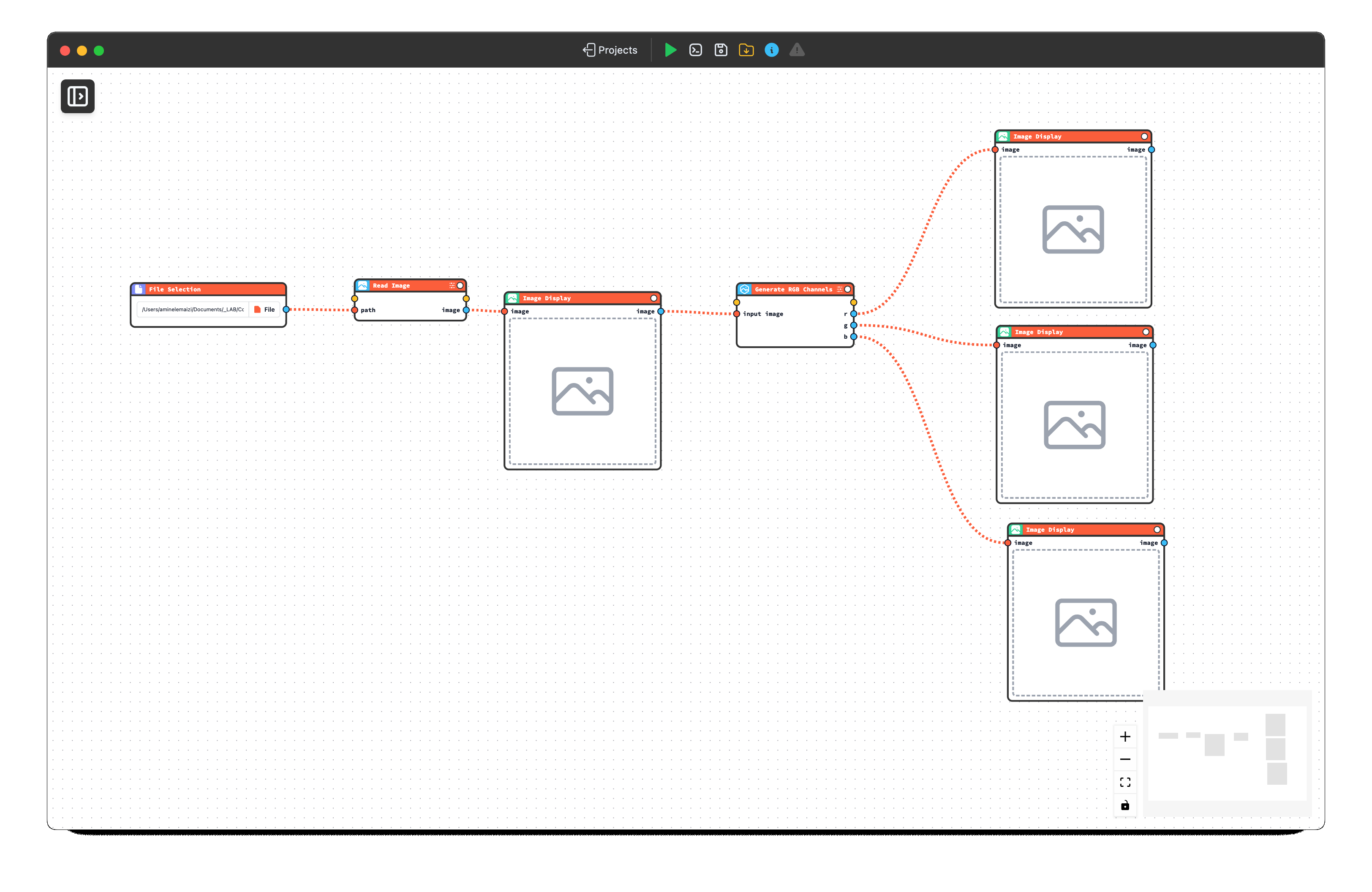
- Drag and Drop: Drag each required brick from the sidebar onto the main graph canvas area.
- Connect Bricks: Create connections by clicking and dragging from an output port (on the right side of a brick) to an input port (on the left side of the next brick). For our example:
- Connect the output of the
File Selectionbrick to the input of theRead Imagebrick. - Connect the output of the
Read Imagebrick to the input of the firstImage Displayto display the original image. - Continue the
Image Displayouput to the input of theGenerate RGB Channelsbrick. - Connect the Red channel output of
Generate RGB Channelsto the input of the secondImage Displaybrick. - Connect the Green channel output to the third
Image Displaybrick. - Connect the Blue channel output to the fourth
Image Displaybrick.
- Connect the output of the
Executing and Monitoring the Flow
With the flow built, you can run it:
Open Logs: Click the Logs button in the Top Action Bar. Keep this window visible to monitor the execution.
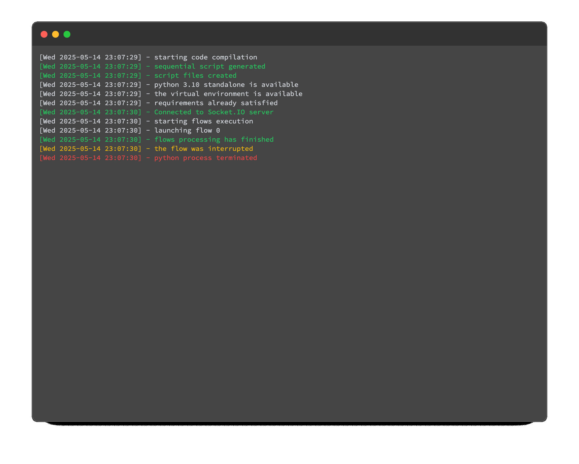
Execute: Click the Execute button in the Top Action Bar.
Monitor: Watch the Logs window. You should see messages indicating the start of the flow, the execution of each brick if they have any logs, and finally, a success message (or error details if something went wrong).
First Execution Time
The very first time you execute a flow within a new project, it might take noticeably longer. This is because CODED FLOWS needs to install any Python package dependencies required by the bricks you've used into the project's dedicated environment. Subsequent executions will typically start much faster as the dependencies are already installed.
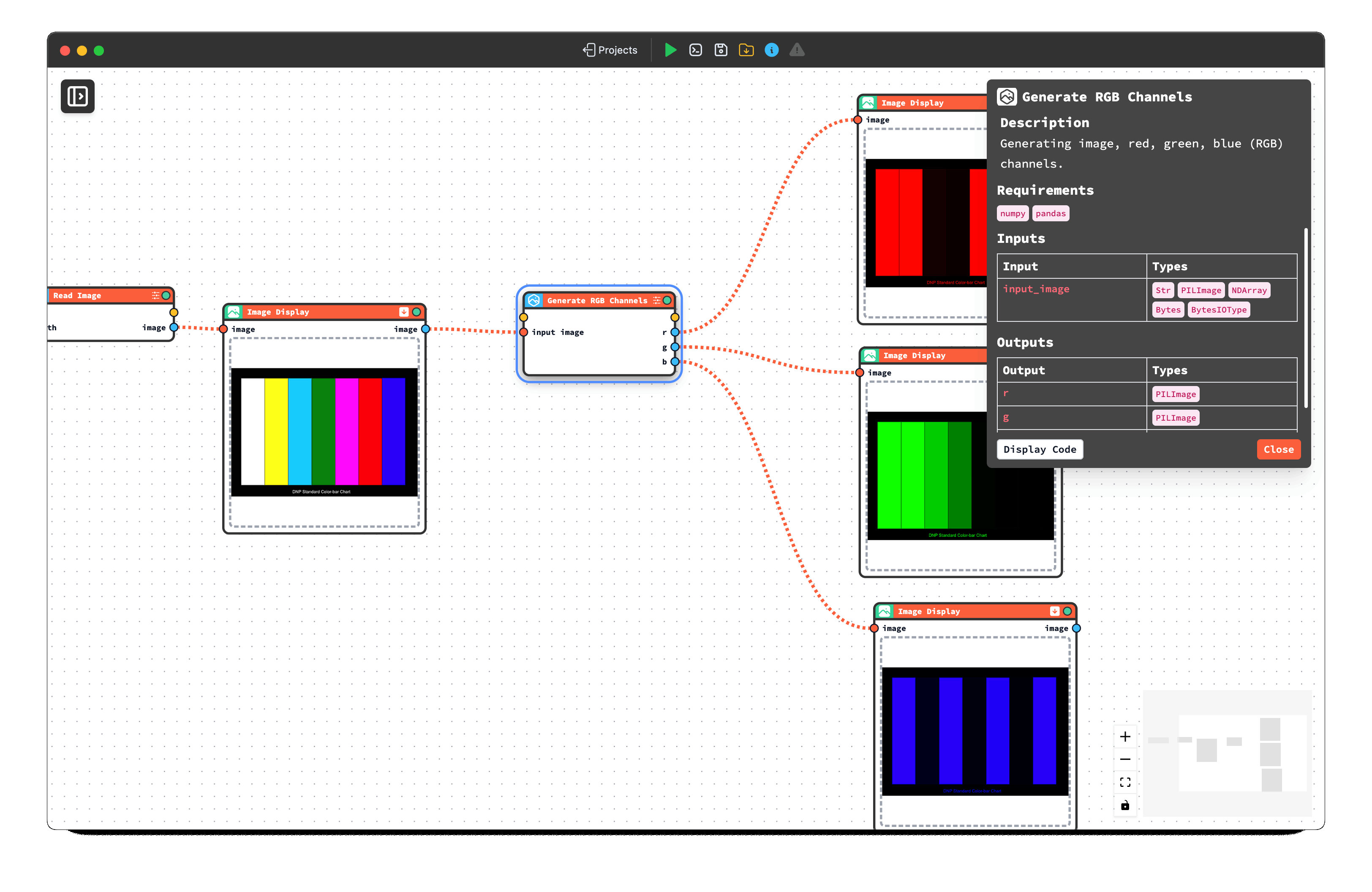
View Results: Once the flow completes successfully, the three
Image Displaybricks should update to show the separated Red, Green, and Blue channel images.
Exporting the Flow as a Python Script
If you need to run your flow logic outside of the CODED FLOWS visual environment (e.g., in a different system, as part of a larger script, or for containerization with Docker), you can export it:
- Save Flow: Ensure your current flow is saved by clicking the Save button.
- Export: Click the Save Script button in the Top Action Bar.
- Check Project Folder: The equivalent Python code of your visual flow will be generated and saved directly into your project folder. You can then use this script independently.
This covers the basics of creating, understanding, building, executing, and exporting a Base Flow in CODED FLOWS. You can now apply these steps to create more complex data processing pipelines.